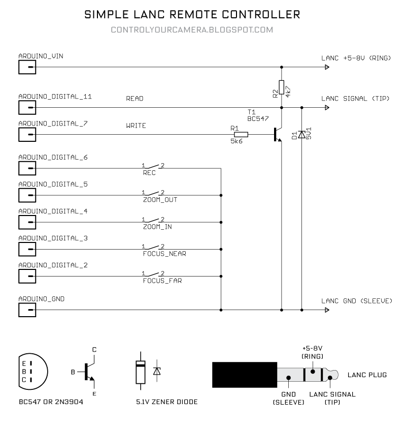
The Arduino sketch below let's you send the REC command, two ZOOM and two FOCUS commands. The LANC commands are arrays containing the bit values for byte 0 and byte 1 of the specific command. All switches should be push buttons.
/*
SIMPLE LANC REMOTE
Version 1.0
Sends LANC commands to the LANC port of a video camera.
Tested with a Canon XF300 camcorder
For the interface circuit interface see
http://controlyourcamera.blogspot.com/2011/02/arduino-controlled-video-recording-over.html
Feel free to use this code in any way you want.
2011, Martin Koch

"LANC" is a registered trademark of SONY.
CANON calls their LANC compatible port "REMOTE".
*/

#define cmdPin 7
#define lancPin 11
#define recButton 6
#define zoomOutButton 5
#define zoomInButton 4
#define focusNearButton 3
#define focusFarButton 2
int cmdRepeatCount;
int bitDuration = 104; //Duration of one LANC bit in microseconds.


//LANC commands byte 0 + byte 1
//Tested with Canon XF300

//Start-stop video recording
boolean REC[] = {LOW,LOW,LOW,HIGH,HIGH,LOW,LOW,LOW,   LOW,LOW,HIGH,HIGH,LOW,LOW,HIGH,HIGH}; //18 33

//Zoom in from slowest to fastest speed
boolean ZOOM_IN_0[] = {LOW,LOW,HIGH,LOW,HIGH,LOW,LOW,LOW,   LOW,LOW,LOW,LOW,LOW,LOW,LOW,LOW}; //28 00
boolean ZOOM_IN_1[] = {LOW,LOW,HIGH,LOW,HIGH,LOW,LOW,LOW,   LOW,LOW,LOW,LOW,LOW,LOW,HIGH,LOW}; //28 02
boolean ZOOM_IN_2[] = {LOW,LOW,HIGH,LOW,HIGH,LOW,LOW,LOW,   LOW,LOW,LOW,LOW,LOW,HIGH,LOW,LOW}; //28 04
boolean ZOOM_IN_3[] = {LOW,LOW,HIGH,LOW,HIGH,LOW,LOW,LOW,   LOW,LOW,LOW,LOW,LOW,HIGH,HIGH,LOW}; //28 06
boolean ZOOM_IN_4[] = {LOW,LOW,HIGH,LOW,HIGH,LOW,LOW,LOW,   LOW,LOW,LOW,LOW,HIGH,LOW,LOW,LOW}; //28 08
boolean ZOOM_IN_5[] = {LOW,LOW,HIGH,LOW,HIGH,LOW,LOW,LOW,   LOW,LOW,LOW,LOW,HIGH,LOW,HIGH,LOW}; //28 0A
boolean ZOOM_IN_6[] = {LOW,LOW,HIGH,LOW,HIGH,LOW,LOW,LOW,   LOW,LOW,LOW,LOW,HIGH,HIGH,LOW,LOW}; //28 0C
boolean ZOOM_IN_7[] = {LOW,LOW,HIGH,LOW,HIGH,LOW,LOW,LOW,   LOW,LOW,LOW,LOW,HIGH,HIGH,HIGH,LOW}; //28 0E

//Zoom out from slowest to fastest speed
boolean ZOOM_OUT_0[] = {LOW,LOW,HIGH,LOW,HIGH,LOW,LOW,LOW,   LOW,LOW,LOW,HIGH,LOW,LOW,LOW,LOW}; //28 10
boolean ZOOM_OUT_1[] = {LOW,LOW,HIGH,LOW,HIGH,LOW,LOW,LOW,   LOW,LOW,LOW,HIGH,LOW,LOW,HIGH,LOW}; //28 12
boolean ZOOM_OUT_2[] = {LOW,LOW,HIGH,LOW,HIGH,LOW,LOW,LOW,   LOW,LOW,LOW,HIGH,LOW,HIGH,LOW,LOW}; //28 14
boolean ZOOM_OUT_3[] = {LOW,LOW,HIGH,LOW,HIGH,LOW,LOW,LOW,   LOW,LOW,LOW,HIGH,LOW,HIGH,HIGH,LOW}; //28 16
boolean ZOOM_OUT_4[] = {LOW,LOW,HIGH,LOW,HIGH,LOW,LOW,LOW,   LOW,LOW,LOW,HIGH,HIGH,LOW,LOW,LOW}; //28 18
boolean ZOOM_OUT_5[] = {LOW,LOW,HIGH,LOW,HIGH,LOW,LOW,LOW,   LOW,LOW,LOW,HIGH,HIGH,LOW,HIGH,LOW}; //28 1A
boolean ZOOM_OUT_6[] = {LOW,LOW,HIGH,LOW,HIGH,LOW,LOW,LOW,   LOW,LOW,LOW,HIGH,HIGH,HIGH,LOW,LOW}; //28 1C
boolean ZOOM_OUT_7[] = {LOW,LOW,HIGH,LOW,HIGH,LOW,LOW,LOW,   LOW,LOW,LOW,HIGH,HIGH,HIGH,HIGH,LOW}; //28 1E

//Focus control. Camera must be switched to manual focus
boolean FOCUS_NEAR[] = {LOW,LOW,HIGH,LOW,HIGH,LOW,LOW,LOW,   LOW,HIGH,LOW,LOW,LOW,HIGH,HIGH,HIGH}; //28 47
boolean FOCUS_FAR[] = {LOW,LOW,HIGH,LOW,HIGH,LOW,LOW,LOW,   LOW,HIGH,LOW,LOW,LOW,HIGH,LOW,HIGH}; //28 45

boolean FOCUS_AUTO[] = {LOW,LOW,HIGH,LOW,HIGH,LOW,LOW,LOW,   LOW,HIGH,LOW,LOW,LOW,LOW,LOW,HIGH}; //28 41

//boolean POWER_OFF[] = {LOW,LOW,LOW,HIGH,HIGH,LOW,LOW,LOW,   LOW,HIGH,LOW,HIGH,HIGH,HIGH,HIGH,LOW}; //18 5E
//boolean POWER_ON[] = {LOW,LOW,LOW,HIGH,HIGH,LOW,LOW,LOW,   LOW,HIGH,LOW,HIGH,HIGH,HIGH,LOW,LOW}; //18 5C  Doesn't work because there's no power supply from the LANC port when the camera is off
//boolean POWER_OFF2[] = {LOW,LOW,LOW,HIGH,HIGH,LOW,LOW,LOW,   LOW,LOW,HIGH,LOW,HIGH,LOW,HIGH,LOW}; //18 2A Turns the XF300 off and then on again
//boolean POWER_SAVE[] = {LOW,LOW,LOW,HIGH,HIGH,LOW,LOW,LOW,   LOW,HIGH,HIGH,LOW,HIGH,HIGH,LOW,LOW}; //18 6C Didn't work


void setup() {

 pinMode(lancPin, INPUT); //listens to the LANC line
 pinMode(cmdPin, OUTPUT); //writes to the LANC line

 pinMode(recButton, INPUT); //start-stop recording button
        digitalWrite(recButton, HIGH); //turn on an internal pull up resistor
        pinMode(zoomOutButton, INPUT);
        digitalWrite(zoomOutButton, HIGH);
        pinMode(zoomInButton, INPUT);
        digitalWrite(zoomInButton, HIGH);
        pinMode(focusNearButton, INPUT);
        digitalWrite(focusNearButton, HIGH);
        pinMode(focusFarButton, INPUT);
        digitalWrite(focusFarButton, HIGH);

        digitalWrite(cmdPin, LOW); //set LANC line to +5V
        delay(5000); //Wait for camera to power up completly
        bitDuration = bitDuration - 8; //Writing to the digital port takes about 8 microseconds so only 96 microseconds are left for each bit
}

void loop() {


   if (!digitalRead(recButton)) {
    lancCommand(REC);
  }

  if (!digitalRead(zoomOutButton)) {
    lancCommand(ZOOM_OUT_4);
  }

  if (!digitalRead(zoomInButton)) {
    lancCommand(ZOOM_IN_4);
  }

  if (!digitalRead(focusNearButton)) {
    lancCommand(FOCUS_NEAR);
  }

  if (!digitalRead(focusFarButton)) {
    lancCommand(FOCUS_FAR);
  }
}


void lancCommand(boolean lancBit[]) {

        cmdRepeatCount = 0;

   while (cmdRepeatCount < 5) {  //repeat 5 times to make sure the camera accepts the command

                while (pulseIn(lancPin, HIGH) < 5000) {
                  //"pulseIn, HIGH" catches any 0V TO +5V TRANSITION and waits until the LANC line goes back to 0V
                  //"pulseIn" also returns the pulse duration so we can check if the previous +5V duration was long enough (>5ms) to be the pause before a new 8 byte data packet
                  //Loop till pulse duration is >5ms
                }

   //LOW after long pause means the START bit of Byte 0 is here
   delayMicroseconds(bitDuration);  //wait START bit duration

   //Write the 8 bits of byte 0
                        //Note that the command bits have to be put out in reverse order with the least significant, right-most bit (bit 0) first
                        for (int i=7; i>-1; i--) {
     digitalWrite(cmdPin, lancBit[i]);  //Write bits.
     delayMicroseconds(bitDuration);
                        }

                        //Byte 0 is written now put LANC line back to +5V
                        digitalWrite(cmdPin, LOW);
                        delayMicroseconds(10); //make sure to be in the stop bit before byte 1

                        while (digitalRead(lancPin)) {
                          //Loop as long as the LANC line is +5V during the stop bit
                        }

                        //0V after the previous stop bit means the START bit of Byte 1 is here
         delayMicroseconds(bitDuration);  //wait START bit duration

         //Write the 8 bits of Byte 1
                        //Note that the command bits have to be put out in reverse order with the least significant, right-most bit (bit 0) first
                        for (int i=15; i>7; i--) {
              digitalWrite(cmdPin,lancBit[i]);  //Write bits
             delayMicroseconds(bitDuration);
                        }

                        //Byte 1 is written now put LANC line back to +5V
                        digitalWrite(cmdPin, LOW);

   cmdRepeatCount++;  //increase repeat count by 1

   /*Control bytes 0 and 1 are written, now don’t care what happens in Bytes 2 to 7
   and just wait for the next start bit after a long pause to send the first two command bytes again.*/


 }//While cmdRepeatCount < 5
}
Great! thanks!
ReplyDeleteTested it with a Sony TRV 900 E worked right away.
Cheers,
Lourenço
Hi -- Just tested your code with a Sony HDR-CX190 and the interface schematic as presented. Zooms and Record worked beautifully on the first try. Focus options did not. I assume this is a camera specific "feature" although it does not have a "real" manual/auto button -- no reason to think it is related to your code. If I fix this I'll let you know. Also, out of curiosity I tweaked the cmdRepeatCount. On my camera it seemed to work 100% down to cmdRepeatCount<2. Failed 100% at <1; so once is clearly not enough, but various cameras may not need all 5 repeats (but there may well be no advantage in reducing the count from 5). Anyway, GREAT JOB -- THANKS!!!
ReplyDeleteThanks for posting this. Your code is well written and very helpful. I am having some difficulties with my HDR SR 12, but nothing that seems insurmountable. I'm wondering. You recommended playing with delayMicroseconds() values; should I adjust only line 156, or others? Thanks again for all of your hard work.
ReplyDeleteHi Bangalore, I mean experimenting with the bitDuration variable. because writing to the digital port takes *about* 8 microseconds so only 96 microseconds are left for each bit. Therefore the line bitDuration = bitDuration - 8;
ReplyDeleteThanks. Still no luck. I'm wondering if it is because my camera has a D style connector. In order to use LANC, a 100k resistor must be put in between pins 7 (Func control) and pin 3 (GND). LANC works fine with a board I made using designs from http://plazma.kapsi.fi/diy/lanc_controller/index.html
ReplyDeleteBut, I want to get this working with Arduino so as to do some more complex things. Right now, the camera powers up the board, so the resistor is doing its job, but the LANC signal itself seems to be doing nothing. I've played with the bitDuration from 4 to around 15, but still no dice. Any ideas?
Thanks, this worked great! Do you know if this will work with the 3.3v Arduino Fio? Can I use the same transistor and resistors?
ReplyDeleteHi, I'm trying to connect 2 LANC inputs to the Arduino without using the LANC to power the Arduino.
ReplyDeleteI assume that would make the circuit easier however I'm not sure whether I can just ignore the +5-8v from the LANC cable.
The coding I can handle, but the only H/W examples I can find are for a single connection that powers the Arduino.
Any help would be greatly appreciated.
This worked great on both an old Sony DSR-PD170 and newer Canon XF105.
ReplyDeleteDear Martin,
ReplyDeleteYour code works fine with a Canon HF G30 as well. Thanks for publishing!
I tried to control my video camera for capturing still photos. However, I failed. I tested commands like 0x18 0x39, 0x18 0x2B, 0x1E 0x58 and others. My camera does not react. Did you ever test this feature?
Best Regards,
Urs
Dear Urs, thanks for the update. Sorry but I haven't tried contolling still photo shooting.
ReplyDeleteHi, can you make a rc-remote control with the LANC Remote controller?
ReplyDeleteBest Regards
Mike
Hi, can you make a rc-remote control with your LANC Remote controller?
ReplyDeleteBest Regards
Mike
Hi, can you make a rc-remote control for a SONY A5100 with your LANC Remote controller?
ReplyDeleteBest Regards
Mike
i doubt it, i have a A5100 with a cheap lanc controller and nothing responds!
DeleteAny idea if it would be possible to control the absolute zoom position? Maybe by counting the zoom commands?
ReplyDeletethanks
Wolfgang R.
Great code!
ReplyDeleteAnyone know how i can add a RECORD status LED?
Thanks
Add a LED and a resistor to PIN13 as described here https://www.arduino.cc/en/Tutorial/Blink
ReplyDeleteThen make this change to the code:
Above setup() write:
boolean toggle = true;
In loop() add:
if (!digitalRead(recButton)) {
lancCommand(REC);
if (toggle) {
digitalWrite(LED_BUILTIN, HIGH);
toggle = false
} else {
digitalWrite(LED_BUILTIN, LOW);
toggle = true;
}
}
I was change the codes but its not working. Can you write the codes with record led and share pls?
DeleteYes... but i like to have it as a reading of status from the camera.
ReplyDeleteAs you can see i used your code to build my quad pan tilt LANC controler....
ReplyDeletei trigger REC from controller and get a big RECORD on my oled when i toggle a camera...but with 4 cameras it can be confusing and not so sure if it's recording...
That's why i like to have a real reading from camera...
https://forums.vmix.com/default.aspx?g=posts&m=36124#post36124
https://forums.vmix.com/default.aspx?g=posts&m=36185#post36185
Thanks
Thank you for codes, it is work! But I have a question, how I use the zoom controller with spring return potentiometer(like on the camera)? is there a code for this ?
ReplyDeleteThanks a lot for this great info here.
ReplyDeleteThe code works for my Sony HDR-CX305E.
Where I didn't succeed is in getting control over
the zoom step counter. I would like to control
the view without using a remote monitor. Simply
counting the commanded zoom steps.
I played around with the cmdRepeatCount between 2 to 5
loops. There seems no reliable way to command the step
numbers.
Next analysing the status bytes 2-7 was not helpful
as well. Bytes 2-5 are fixed. Byte 6 (probably a counter)
and byte 7 changes in the status. I've spend some time
in finding a pattern to see the zoom stepping reported
there. But no idea.
Does someone has an idea if is or is not possible to
track the absolute zoom factor?
Thanks in advance
Wolfgang R.
Hi Wolfgang,
DeleteDid you checked this link which describes the data structure ?
http://www.boehmel.de/lanc.htm
My problem is that I can't figure out how I can read the status bytes. Can you tell me how do you read these status bytes ? Because I'd like to put a red led when recording, and use the camera status, more reliable than a flag that remembers I've sent a record command without a stop command.
Regards,
Olivier.
Hi Oliver,
DeleteI tested based on this script
http://controlyourcamera.blogspot.com/2011/02/finding-out-lanc-remote-commands.html
But commanding on/off was very reliable. I expect it gets harder by looking at the status.
Here a snippet to look at the status byte
...
/*************** byte 4 *******************/
//0V after the previous stop bit means the START bit of Byte 1 is here
delayMicroseconds(bitDuration); //wait START bit duration
delayMicroseconds(bitDuration/2); //wait until the middle of bit 0 of byte 1
//Note that the command bits have to be read in reverse order with the least significant, right-most bit (bit 0) first
for (int i=7; i>-1; i--) {
lancBit_Byte4[i] = digitalRead(lancPin); //read bits
delayMicroseconds(bitDuration);
}
Serial.println("BITS [4]: ");
for (int i=0; i<8; i++) {
Serial.print((lancBit_Byte4[i]-1)*-1); //invert the bits
}
Serial.println("");
...
HTH
Wolfgang R.
Hi Wolfgang,
DeleteThanx for your reply. I will check that later, as I don't have much time during the week.
Regards,
Olivier.
Hi Wolfgang,
DeleteI had problem with my breadbord for arduino, and I couldn't control the camera.
I don't know where do I have to put the code you mentioned in the program, which is an exact copy of the program top above.
Greetings and thank you for your help.
Olivier.
Hi Olivier,
Deletehere the code I was using.
Wolfgang R.
/*
LANC SNIFFER
Version 1.0
Finds out LANC commands from a REMOTE
For the interface ciruit see
Feel free to use this code in any way you want.
2011, Martin Koch
"LANC" is a registered trademark of SONY.
CANON calls their LANC compatible port "REMOTE".
http://controlyourcamera.blogspot.de/2011/02/finding-out-lanc-remote-commands.html
*/
#define lancPin 9
int bitDuration = 104; //Duration of one LANC bit in microseconds.
int lancBit[16];
int lancBit_Byte2[8];
int lancBit_Byte3[8];
int lancBit_Byte4[8];
int lancBit_Byte5[8];
int lancBit_Byte6[8];
int lancBit_Byte7[8];
void setup() {
Serial.begin(9600); //open the serial port
pinMode(lancPin, INPUT); //listens to the LANC line
delay(5000); //Wait for camera to power up completly
bitDuration = bitDuration- 8; //Reading the digital port takes about 8 microseconds so only 96 microseconds are left for each bit
}
void loop() {
readLancCommand();
delay(1000);
}
void readLancCommand() {
while (pulseIn(lancPin, HIGH) < 5000) {
//"pulseIn, HIGH" catches any 0V TO +5V TRANSITION and waits until the LANC line goes back to 0V
//"pulseIn" also returns the pulse duration so we can check if the previous +5V duration was long enough (>5ms) to be the pause before a new 8 byte data packet
//Loop till pulse duration is >5ms
}
//LOW after long pause means the START bit of Byte 0 is here
delayMicroseconds(bitDuration); //wait START bit duration
delayMicroseconds(bitDuration/2); //wait until the middle of bit 0 of byte 0
//Read the 8 bits of byte 0
//Note that the command bits come in in reverse order with the least significant, right-most bit (bit 0) first
for (int i=7; i>-1; i--) {
lancBit[i] = digitalRead(lancPin); //read bits.
delayMicroseconds(bitDuration);
}
//Byte 0 is read
delayMicroseconds(10); //make sure to be in the stop bit before byte 1
while (digitalRead(lancPin)) {
//Loop as long as the LANC line is +5V during the stop bit
}
//0V after the previous stop bit means the START bit of Byte 1 is here
delayMicroseconds(bitDuration); //wait START bit duration
delayMicroseconds(bitDuration/2); //wait until the middle of bit 0 of byte 1
//Read the 8 bits of Byte 1
//Note that the command bits have to be read in reverse order with the least significant, right-most bit (bit 0) first
for (int i=15; i>7; i--) {
lancBit[i] = digitalRead(lancPin); //read bits
delayMicroseconds(bitDuration);
}
//Byte 1 is read
//Print byte 0 and byte 1 to the Serial Monitor console of the Arduino developing environment
Serial.println("BITS: ");
for (int i=0; i<16; i++) {
Serial.print((lancBit[i]-1)*-1); //invert the bits
if (i==7) Serial.print(" ");
}
Serial.println("");
/*************** byte 4 *******************/
//0V after the previous stop bit means the START bit of Byte 1 is here
delayMicroseconds(bitDuration); //wait START bit duration
delayMicroseconds(bitDuration/2); //wait until the middle of bit 0 of byte 1
//Note that the command bits have to be read in reverse order with the least significant, right-most bit (bit 0) first
for (int i=7; i>-1; i--) {
lancBit_Byte4[i] = digitalRead(lancPin); //read bits
delayMicroseconds(bitDuration);
}
Serial.println("BITS [4]: ");
for (int i=0; i<8; i++) {
Serial.print((lancBit_Byte4[i]-1)*-1); //invert the bits
}
Serial.println("");
}
I had to shorten the code as it was too long for posting here. You have to supply all blocks, not only _Byte4
Deleteint lancBit_Byte2[8];
int lancBit_Byte3[8];
int lancBit_Byte4[8];
int lancBit_Byte5[8];
int lancBit_Byte6[8];
int lancBit_Byte7[8];
Hi Wolfgang,
DeleteI couldn't fix my board yet, but I analyzed the code you supplied.
Why don't you make a loop to read the 8 bytes ? (i.e. for i = 0 to 7 ...) Instead of duplicating the code ? Is there a reason for that ?
Thank you.
Hello I am from Argentina.
ReplyDeleteI'm testing on a Cannon HF G10 and it works. I only have one problem, the zoom is not fluid, has jumps (tug); Why can this happen?
Greetings and thanks for sharing.
Best instruction
ReplyDeleteThis work for many sony camera.
I think for variable speed example joystick for change zoomin and zoomout button
Btw thank's martin
Can I simly leave out the Ring part if my arduino gets powered seperatly?
ReplyDeleteI have the same question. I don't believe my BMPCC has enough current at the lanc plug to power the Arduino Uno. As JoniBoni ask, can we leave the power ring disconnected. And then power the Arduino with a 9v battery?
ReplyDeleteYou may use the usb input to power the board.
DeleteWhat is the iris (diafragma) "Open & Close" CODE, on Sony?
ReplyDelete